
Slew-rate Control
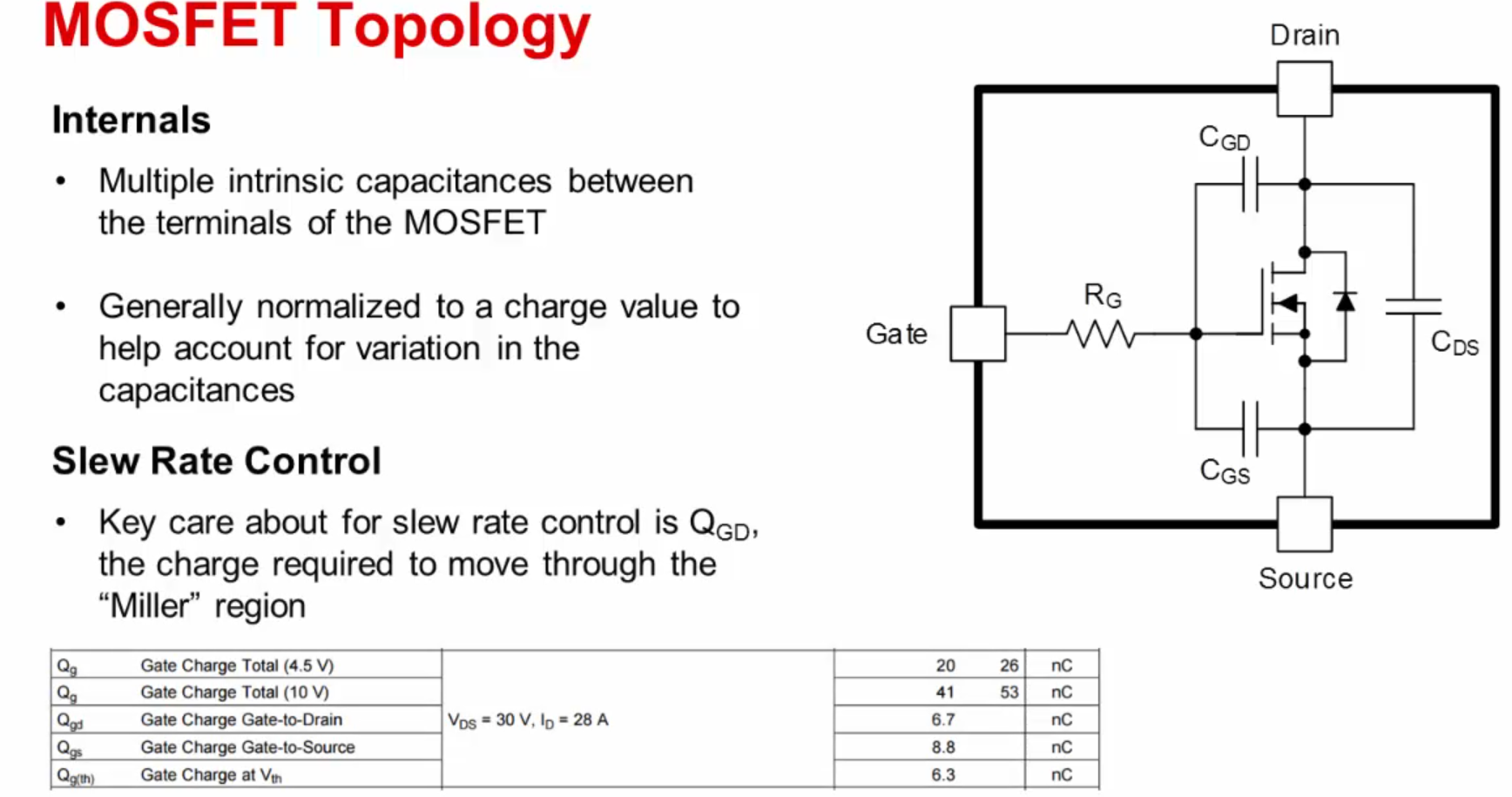
Slew-rate means the slope of the VDS for the mosfet
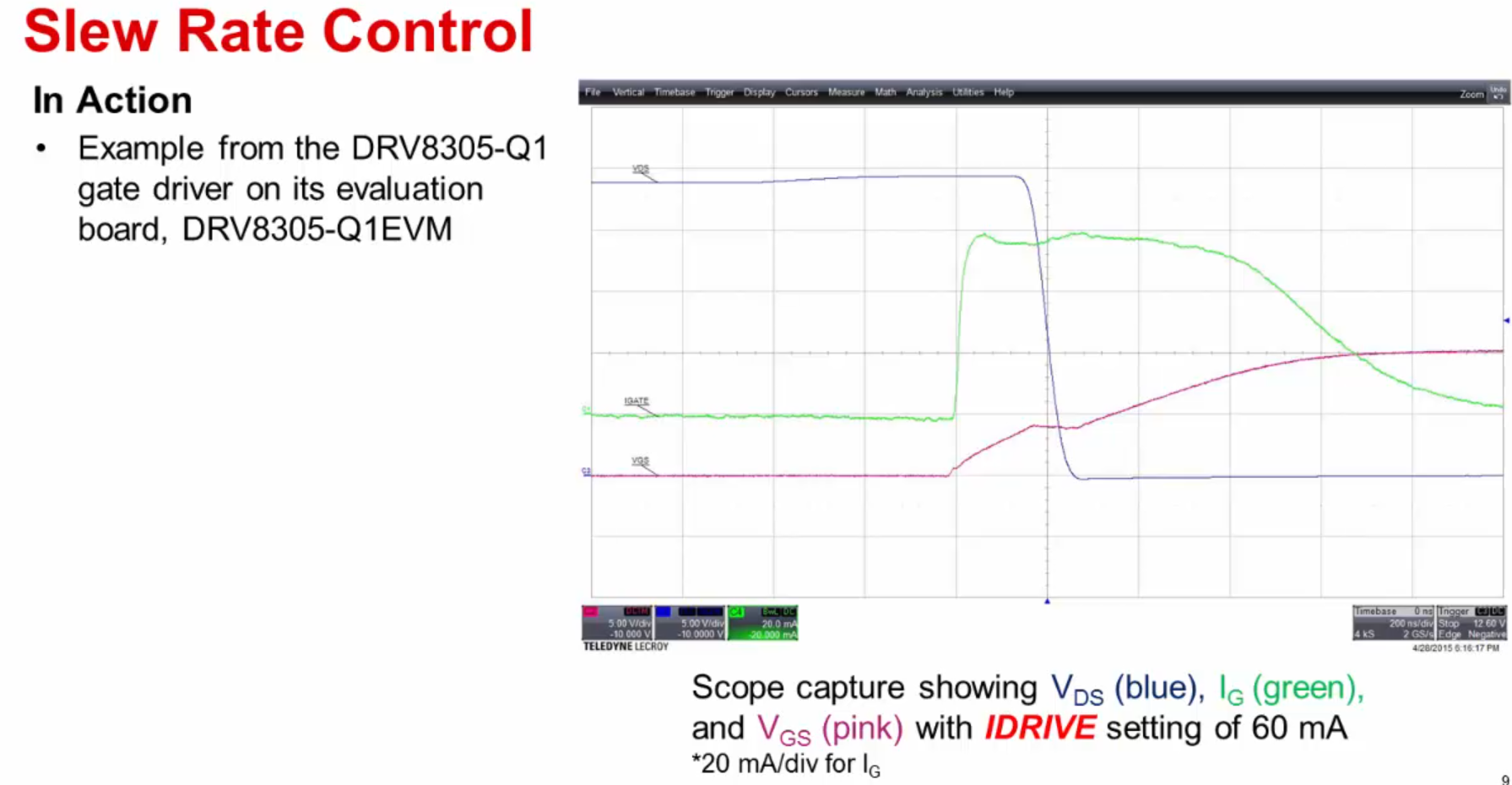
Driver for mosfet control
Capacitors
R3 based on (val wasnt mentioned)8.3.1.2.1 Serial Peropheral Interface
R4 based on Figure 34 (val wasnt mentioned)
C6 (X5R or X7R, 1-μF, 16-V ceramic capacitor) and C5 (X5R or X7R, 47-nF, VM-rated ceramic capacitor) based on 8.3.1.3 Gate Driver Voltage Supplies
C6 suggested to be split in two CVM1(X5R or X7R, 0.1-μF, VM-rated capacitor) and CVM2 (≥ 10 μF, VM-rated capacitor)in 8.3. Feature description
C6 (A 0.1-μF ceramiccapacitorratedfor VM mustbe placedas closeto the deviceas possible) 10 PowerSupplyRecommendations
C7 (X5R or X7R, 1-μF, 6.3-V ceramic capacitor routed directly back to the adjacent AGND ground pin) according to 8.3.2 DVDD Linear Voltage Regulator
VREFCAP (X5R or X7R, 0.1-μF, VREF-rated capacitor) in 8.3. Feature description
nSHDN (suggested to be attached with the 100kOhm resistor to protect the device in case of larger input voltage) but in the design left floating from 8.3.4EnableSHDNand VIN UndervoltageLockout from the LMR16006 datasheet
C17 and C2 not clear how it was chosen (X5R or X7R, 1 to 10 μF, VM-rated capacitor suggested) from 8.3. Feature description
Buck-boost
Elements for Buck-Boost configuration can be seen in 9.2 TypicalApplication from LMR16006 datasheet
If calculated with 0.6 max current and 40% K_id and max voltage 24V, the inductor minimum value should be bigger - 23.8uH
Output capacitance is likely ok, only minimum value can be calculated, but the datasheet sugests to experiment with values up to 100uF as stated in 9.2.2.3 Output Capacitor Selection
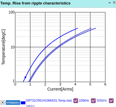
Regarding input capacitance. If 10uF is chosen (suggested is value between 1uF and 10uF). Then the ripple current calculated is 0.25A and the input voltage deviation is 21mV. Capacitor ripple current must be greater then calculated. Based on the datasheet for 10uF capacitor from original design, the only concern is rise of the temperature when working in AC conditions, and based on the Temperature-Arms graph 0.25A is well inside the safe limit for this capacitor.
Resistors are taken from typical application and the output is fixed based on the resistance values(doesnt scale depending on input). How to calculate resistors is explained in 8.3.3 Output Voltage Setting
3.3 V linear generator
MC1 according to suggestion from LDFM33PUR datasheet
C19 and C20 (both 22 uF) not according to Stable ESR zone, in LDFM33PUR datasheet stated max value 22uF in Figure 26: Stability plane 3.3 V (COUT, ESR)